Foreword
As a large number of nonlinear electrical equipment such as power electronic devices are connected to the power grid, the harmonic current generated by them will be injected into the power grid, which will distort the voltage waveform of the public power grid, affect the power quality of the power grid, and threaten the safe and economic operation of electrical equipment in the power grid. Therefore, power factor correction (PFC) is needed to control the harmonic content of the public power grid within the allowable range, to prevent the harmonic from harming the power grid and electrical equipment, and to ensure the safety and economic operation of the power grid, so as to obtain good economic benefits.
Totem column bridgeless PFC (except the traditional low-frequency rectifier bridge) has the characteristics of less components and low common-mode noise. Due to the poor reverse recovery characteristics of ordinary Si MOSFET body diodes, totem-pole bridgeless PFC usually works in CRM or DCM to avoid additional losses caused by reverse recovery. This mode of PFC has large inductor ripple current and large EMI filter volume, so it can only be adopted in medium and small power occasions. SiC devices have the advantages of good reverse recovery performance, high temperature resistance and fast switching speed, so there are a large number of projects in the fields of vehicle OBC, communication power supply, UPS and high-frequency DC-DC that use totem pole bridgeless PFC instead of traditional PFC or staggered parallel PFC.
Topology analysis of totem pole without bridge
Fig. 1 is a basic circuit power stage structure based on SiC totem pole PFC, in which Q1 and Q2 are SiC MOSFET operating at system high frequency, Q3 and Q4 are common super-junction MOSFETs operating at grid frequency, and Schottky diodes connected in parallel with Q3 and Q4 are used to further improve system efficiency.
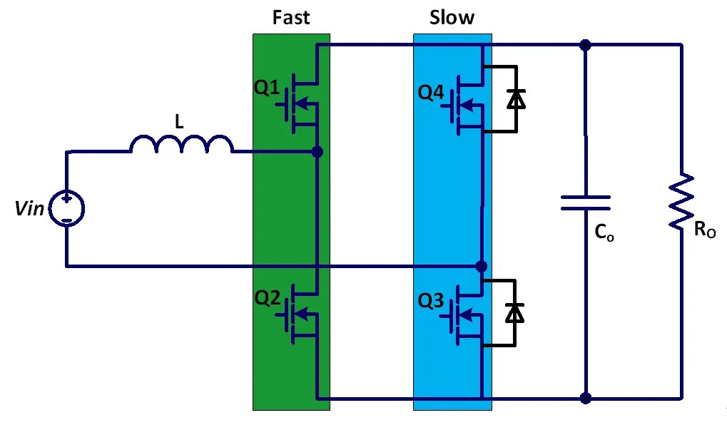
Figure 1 Basic structure of totem pole PFC
When the input voltage vin is in the positive half cycle, the main switch tube is Q2, with a duty ratio of D, and the freewheeling switch tube is Q1, with a duty ratio of 1-D; Inductive energy storage, flowing through Q2, Q3, L to Vin;; When the inductor releases energy, the main switching tube Q2 is closed, and the freewheeling tube Q1 is opened, flowing through L, Q1, Ro and Q3. The PWM driving waveforms of them are complementary mode PWM, with a dead zone in the middle. The control loop is used to control the duty ratio d of Q2. At this stage, the slow transistor Q3 will always be on, and the inductor current will go from left to right. As shown in Figure 2 below, the inductive energy storage and free-wheeling path in the positive half cycle of AC are given.
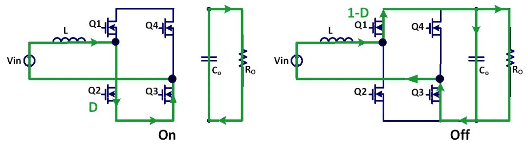
Fig. 2 Current path in positive half cycle of grid voltage
When the input voltage vin is in the negative half cycle, the main switch tube is Q1, and its duty cycle is D, and the freewheeling switch tube is Q2, and its duty cycle is 1-D; Inductor reverse energy storage, flowing through Q4, Q1, L to Vin;; When the inductor releases energy, the main switching tube Q1 is closed, and the freewheeling tube Q2 is opened, flowing through Q2, L, Vin, Q4 and Ro. The PWM driving waveforms of them are complementary mode PWM with a dead zone in the middle, and the control loop controls the duty ratio d of Q1. At this stage, the slow transistor Q4 will always be on, and the inductance current will go from right to left, as shown in Figure 3 below, and the path of inductance energy storage and freewheeling during the negative half cycle of AC is given.
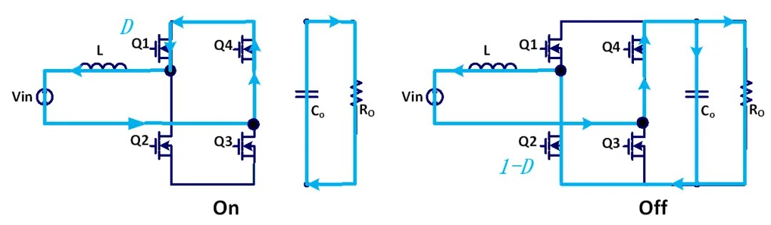
Fig. 3 Current path in negative half cycle of grid voltage
Design of driving circuit
SiC MOSFET has the advantages of high voltage resistance, high temperature resistance, low conduction and high working frequency, but its advantages also bring some problems at high frequency. With the increase of switching frequency, the voltage change rate (dv/dt) of SiC MOSFET in turn-off process becomes larger, which is coupled to the gate through Miller capacitor Cgd, resulting in voltage change of the gate. If the voltage change exceeds the turn-on threshold voltage Vth, it will lead to the second turn-on of SiC MOSFET, so SiC MOSFET needs to be turned off under negative pressure to avoid this phenomenon. Usually, the turn-off voltage is set at -2 to -4V.
The switching speed of SiC MOSFET is mainly determined by the magnitude of its gate-source capacitance Cgs and the charge-discharge current of the driving circuit, and the magnitude of Cgs is certain, while the charge-discharge current is related to the driving voltage and gate resistance. In order to obtain faster switching speed and improve the working efficiency of the system, a small driving resistor is usually selected to increase the gate driving current, and too small driving resistor may lead to over-oscillation of the gate-source voltage (especially in Miller platform). Since the gate drive is a typical RLC structure, the minimum resistance to ensure that the gate does not oscillate can be derived:

Lwire gate inductance includes the connection inductance (PCB) between the driver and the device, and the parasitic inductance inside the device gate. In circuit design, the gate resistance can be reduced by reducing the connection inductance, and the range of driving resistance can be increased.
System verification results:
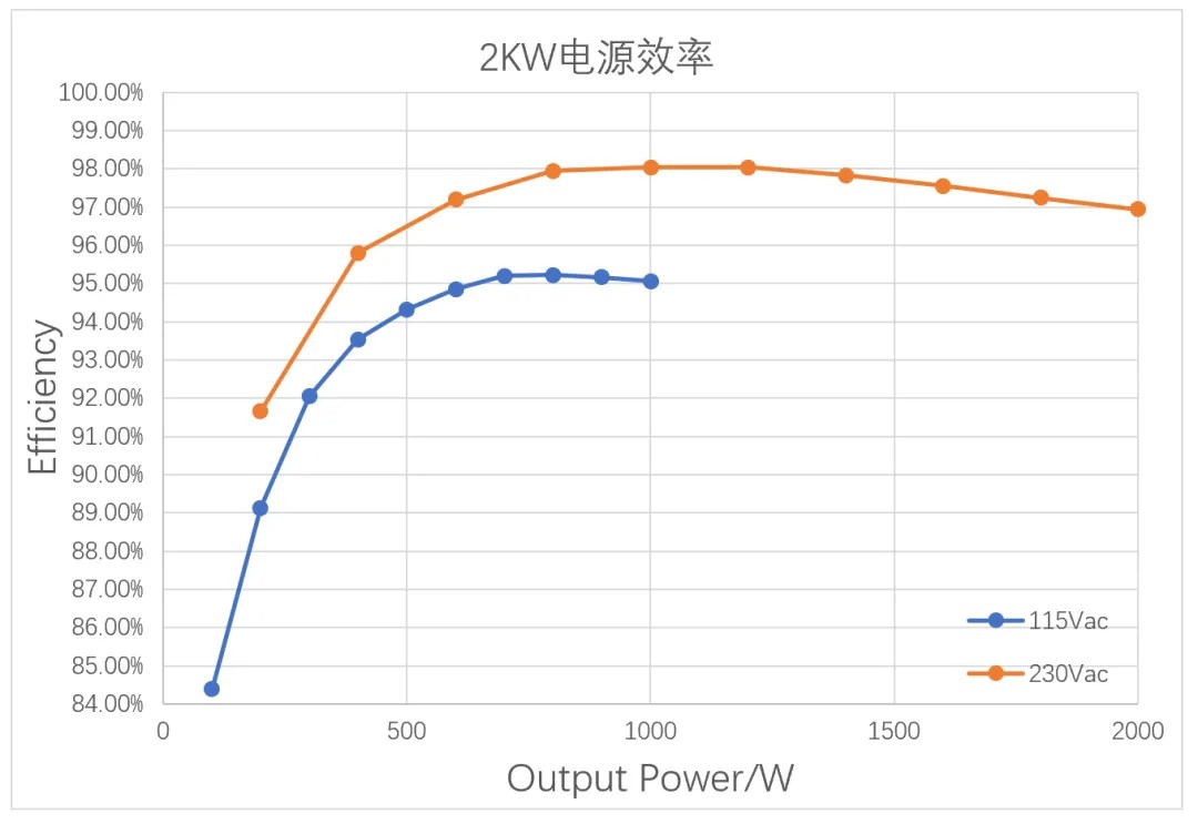
Verified on a 2KW power supply (rated input voltage is 230Vac, rated output is 48Vdc), the power supply architecture adopts totem PFC+ full bridge LLC, the working frequency of PFC is 65 kHz, and CCM control is adopted, and the SiC MOSFET adopts 650V/45mΩ. The measured peak efficiency exceeds 98%(230Vac@1000W), which reaches the titanium efficiency standard. Compared with the traditional staggered PFC power supply scheme controlled by CRM, it is limited.
Alkaidsemi provides a full range of 650V SiC MOS.

As a large number of nonlinear electrical equipment such as power electronic devices are connected to the power grid, the harmonic current generated by them will be injected into the power grid, which will distort the voltage waveform of the public power grid, affect the power quality of the power grid, and threaten the safe and economic operation of electrical equipment in the power grid. Therefore, power factor correction (PFC) is needed to control the harmonic content of the public power grid within the allowable range, to prevent the harmonic from harming the power grid and electrical equipment, and to ensure the safety and economic operation of the power grid, so as to obtain good economic benefits.