Introduction
As is well known, power semiconductor devices are a great helper in energy conservation and emission reduction, helping to achieve carbon neutrality goals. In recent years, frequency converters have been increasingly used in household appliances, and at the same time, large power supplies for industrial equipment also need to reduce power consumption. Therefore, the demand for high-efficiency switching devices is constantly increasing. All of these have given rise to the demand for low loss switching devices and higher switching frequencies.
1. Introduction to the New Platform
1.1 Platform Technical Characteristics
Alkaidsemi has launched a new 650V S3 platform T series IGBT single tube, which has been specially optimized for short-circuit withstand and equipped with full current fast recovery diodes. The T series IGBT single tube, with its overall best IGBT saturation voltage and diode forward voltage performance, enables the system to have lower power consumption and better thermal performance. It is the best product in the fields of home appliances and industrial motor drives, and is suitable for various applications including UPS/PV and PFC. Taking the 650V 75A S3 T series single tube as an example, it is mainly used in industrial motor drive and PV fields, so it has high requirements for short-circuit tolerance and conduction voltage drop Vcesat; This product has a short-circuit withstand time of up to 7 μ s under testing conditions of VCC=330 V, Tvj=25 ° C, and VGE=15V, which is compatible with most motor applications. Compared to the 650V 75A S3 H series single tube, the Vcesat of this product is as low as 1.4V, resulting in a significant increase in static losses of the device.
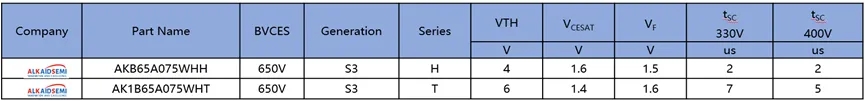
Figure 1 Comparison of AKS 650V IGBT S3 Technology
1.2 Product Distribution

Figure 2 AKS 650V S3 IGBT T series products
The 650V S3 T technology platform has multiple specifications ranging from 5 to 75A and different packaging forms to match different topology circuit applications.
2. Technical Parameter
2.1 Saturation Voltage

Figure 3 AKS 650V S3 IGBT VCEsat: H series VS T series
Alkaidsemi has introduced the latest micro groove and backside thinning processes in the new T series IGBT AK1B65A075WHT, further reducing the saturation voltage VCEsat. Compared with the 650V S3 platform H-series IGBT single tube, its VCEsat decreased by 13% under test conditions of IC=75A, VGE=15V, and TC=25 ℃. Especially for motor applications with low switching frequencies, the losses in terminal applications will be significantly reduced.
2.2 Short Circuit Withstand Time
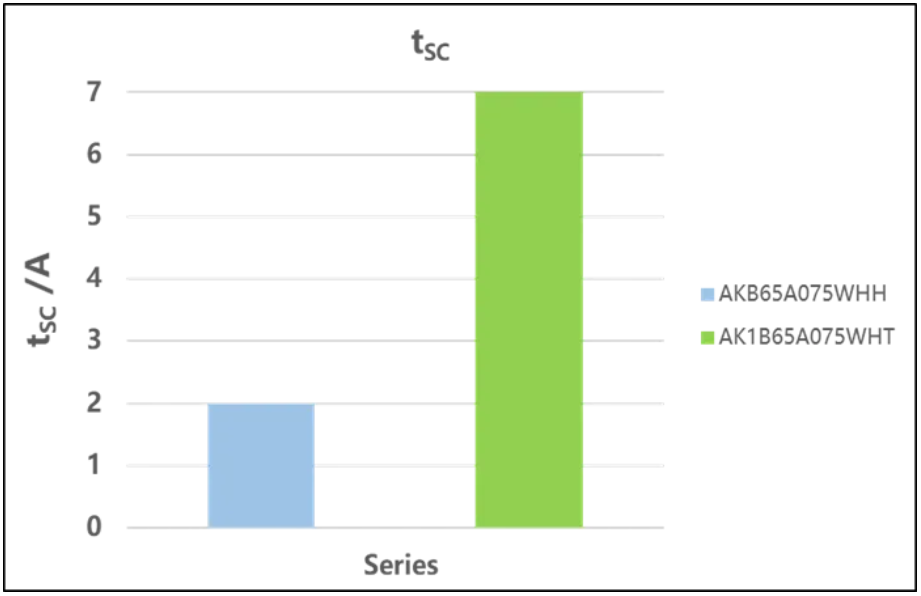
Figure 4 AKS 650V S3 IGBT short-circuit withstand time: H series VS T series
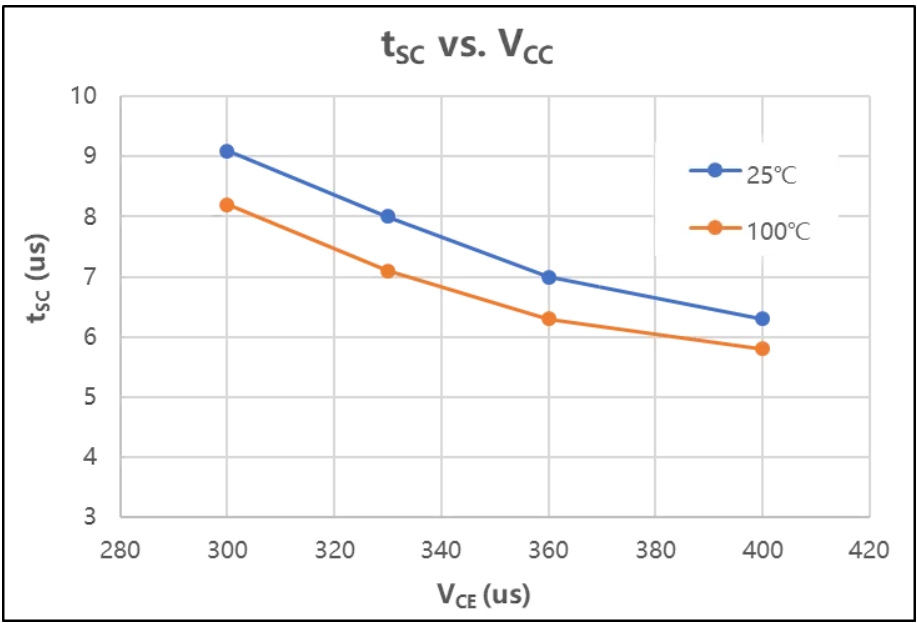
Figure 5 Actual measurement of AKS 650V S3 IGBT T short-circuit withstand time

Figure 6 AKS 650V S3 IGBT T short-circuit safe working area
Under the test conditions of VCC=330V, Tvj=100 ° C, and VGE=15.0V, the single tube short-circuit withstand time of 650V 75A S3 T series is 7 μ s, which is suitable for most applications. According to VCC or Tvj application conditions, this series of single tubes can be used within a safe operating range of 3-6.5 seconds (as shown in Figure 6). Under a certain short-circuit capability, the performance of the 650V 75A S3 T series single tube is further improved, resulting in lower power consumption and better thermal performance of the system.
3. Product Application
3.1 Switching speed (dVce/dt, dIc/dt)
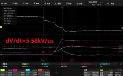
In the application cases of household appliances such as air conditioners, refrigerators, washing machines, etc., the limitations of EMC (electromagnetic compatibility) and the design concept of not using filters or minimizing filters to save costs are limited. AK1B65A015WHT at Tvj=125 ℃, VCC=400V, VGE=15V, RGon=8Ω, RGoff=8Ω, IC=75A, dv/dt controlled at 5.58Kv/us to reduce the high-order harmonic components of the rising and falling edges of the switch.
Although this solution may increase the losses of IGBT during the switching process, the increased losses are not high due to the low switching frequency of this type of switch.
3.2 Crossfire
In half bridge applications, especially in zero voltage turn off applications, crosstalk misleads the conduction problem. When the upper tube is opened, the Vce of the lower tube will suddenly rise, causing Vge to suddenly rise due to the Miller charge Qgc charging. When Vth is exceeded, the IGBT will gradually open. To suppress the increase in Vge height, it is often recommended to turn off negative pressure. When using zero voltage shutdown, it is recommended to connect GE in parallel with RC, where the C value is often 1-2 times the CIES capacitance value. The R value is 0-5 Ω (note that the RC should be close to the GE pin, with the minimum loop area).