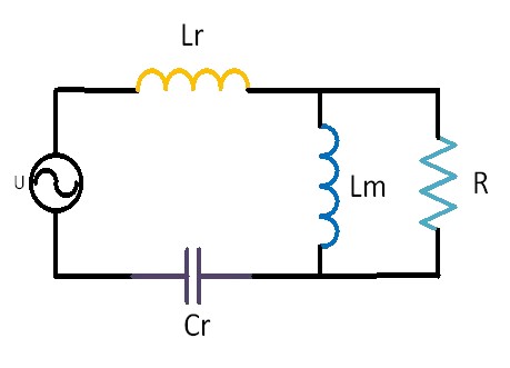
Figure 1 LLC Equivalent Circuit
Figure 1 shows the equivalent circuit diagram of LLC. Compared with the RLC resonant circuit, the LLC circuit only has one additional Lm, which is the excitation inductance of the transformer and will participate in the resonance of Lr and Cr.
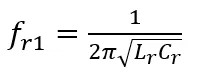
The frequency point at which the inductive reactance of Lr and the capacitive reactance of Cr cancel each other out is called fr1, expressed as:
When the input frequency is at fr1, Lr and Cr undergo series resonance, and Lr and Cr are equivalent to a short circuit, as shown in Figure 2. At this point, regardless of the Q value, the red dashed box inductor Lm and the load R are both inductive when connected in parallel. Therefore, from the input end, the impedance appears inductive, and the resonant circuit operates in the desired inductive state. At this frequency, the output load (R) is independent of gain.
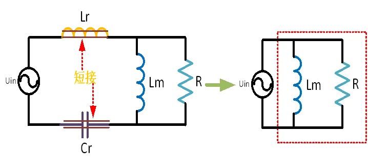
Figure 2 Equivalent circuit when f=fr1
Similarly, there must also be a frequency point where the capacitance of Cr is offset by the total inductance of Lr+Lm, and this frequency point is called fr2, expressed as:
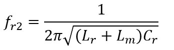
Since Lr+Lm is greater than Lr, the frequency of fr2 must be lower than that of fr1.
In the case where the parameters of resonant elements such as resonant inductor Lr, resonant capacitor Cr, and excitation inductor Lm have been determined, as the Q value continues to decrease, it means that the load becomes lighter until it reaches an unloaded state, where the load R is infinitely large and the Q value approaches zero. The branch connecting the load is equivalent to an open circuit, as shown in Figure 3.
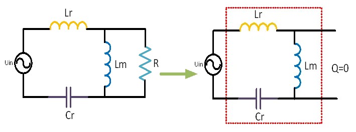
Figure 3 Equivalent circuit of resonant network when Q value changes
At this point, the input impedance Zin is represented by a red dashed box. At the frequency point fr2 where resonance occurs in Lr, Cr, and Lm, the resonant network is equivalent to a short circuit. Therefore, at this frequency point, the output voltage is infinitely large, which is also a point that many operating conditions avoid.
When the input frequency is less than fr2, the capacitive reactance is greater than the total inductive reactance of Lm+Lr, so 0-fr2 is the capacitive region. Conversely, when the input frequency is to the right of fr1, the inductive reactance of Lr is greater than the capacitive reactance of Cr, so frequencies greater than fr1 are in the inductive region, as shown in Figure 4.
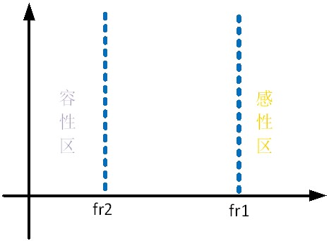
Figure 4 Frequency distribution of working characteristics
When the input frequency is between fr2 and fr1, its operating characteristics vary with the load. When the load is unloaded, R is infinite, and when the output is short circuited, R is infinitely small.
When R is infinite, it is equivalent to an open circuit of R, and the equivalent circuit is shown in Figure 3. At this point, fr2 is the boundary line, 0-fr2 is the capacitive region, and greater than fr2 is the inductive region.
When R is short circuited, it is equivalent to a short circuit Lm, as shown in Figure 4. At this time, fr1 is the boundary line. When the input frequency is between fr2 and fr1, it is the capacitive region, and when it is greater than fr1, it is the inductive region.
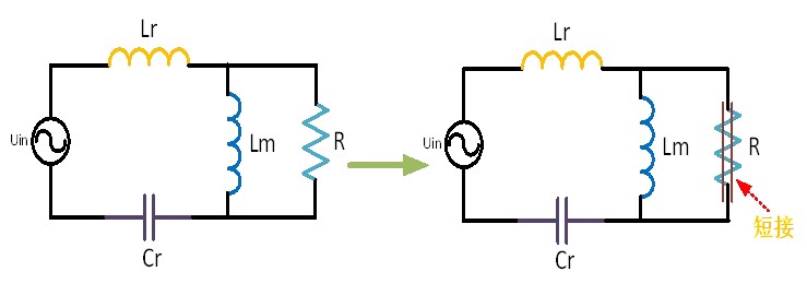
Figure 5 Equivalent circuit of resonant network during short circuit
From the two extreme cases of Rac open circuit and short circuit, it can be seen that the frequency of the inductive and capacitive regions corresponding to different loads is different. Therefore, when the frequency is between fr2 and fr1, different R correspond to different inductive and capacitive operations.
F is the input frequency, summarize the characteristics of LLC circuits at different frequencies:
1、When f>fr1, the resonant circuit must be inductive;
2、When f, the resonant circuit must be capacitive;
3、When fr2 occurs, the resonant circuit may be capacitive or inductive (depending on the frequency and magnitude of R).
In fr2, it is difficult to distinguish between sensibility and capacitance, and only two extremes of R can be determined, one is infinity and the other is infinitesimal. However, at this point, it is impossible to determine other values of R from the principle of the circuit, and it needs to be determined through formula methods. The imaginary number mentioned earlier can be used to determine whether the current in the resonant circuit is inductive or capacitive by simply requiring the complex form of the current, i.e. I=a+bj.
If working in the inductive region, the phase of the current lags behind the voltage, and if the phase of the current leads the voltage, then working in the capacitive region.