LLC resonant converter is widely used in automobile and industry because it can realize the functions of electrical isolation, high efficiency, high power density and low EMI. Because of its multi-mode operation and complicated design and calculation, its equivalent circuit analysis is usually used. Because the equivalent circuit of LLC is very similar to the basic circuit diagram of RLC, the main difference is that their input sources are different and LLC has an Lm inductor, but its resonance principle is the same. In order to facilitate analysis and understanding, we might as well start with the basic principle of RLC.
The resistance of inductance to traffic straightness
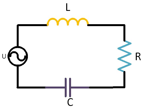
Figure 1 RLC circuit diagram
In RLC loop, RLC can be regarded as an impedance, which is usually represented by Zin. Zin=XL+XC+R, XL stands for inductive reactance, XC stands for capacitive reactance, and R stands for pure resistance. The inductance formula of inductance is XL=2πfL. From the formula, we can see that inductance XL is closely related to frequency as well as inductance. When the inductor is connected to the DC circuit, because the magnitude and direction of the DC current are constant, the magnetic flux in the inductor coil does not change. According to Faraday's law of electromagnetic induction, there is no induced electromotive force. At this time, the inductance has no hindrance to DC current, which is equivalent to a wire, and DC can pass smoothly. When the inductor is connected with alternating current, the magnitude and direction of alternating current change periodically with time, which will make the magnetic flux in the inductor coil change constantly, thus generating induced electromotive force. According to Lenz's law, the induced electromotive force will hinder the change of current, which is manifested as the resistance of inductance to alternating current. This resistance is called inductive reactance (XL), and its size is directly proportional to the frequency (F) and inductance (L) of alternating current. The higher the frequency, the greater the inductance, the greater the inductive reactance, and the stronger the obstacle to alternating current.
Direct-cross characteristics of capacitors
Contrary to inductance, the basic characteristic of capacitance is that it is separated from direct current and alternating current. When DC voltage is applied across the capacitor, the charging process is completed in a very short time. When the capacitor is charged, there is no current flowing in the circuit, because the DC voltage can't keep the charge moving between the plates of the capacitor, so the capacitor is equivalent to an open circuit for DC, which plays a role in isolating DC.
In an AC circuit, with the periodic change of the magnitude and direction of the AC voltage, the capacitor will continuously charge and discharge. Because the direction of AC voltage is constantly changing, there is always current in the circuit, as if AC can pass through the capacitor smoothly. The blocking effect of capacitance on alternating current is called capacitive reactance (XC=1/2πfC), and the magnitude of capacitive reactance is related to the frequency (f) of alternating current and the capacitance value (c). The higher the frequency, the larger the capacitance, the smaller the capacitive reactance, and the easier it is for alternating current to pass through. This is the pass-through characteristic of the capacitor.
Complex forms of inductive reactance and capacitive reactance
Complex numbers are very common in resonant circuits. The real part is called resistance and the imaginary part is called reactance (collectively called capacitive reactance and inductive reactance). The complex formula of XL and capacitive reactance XC is as follows:
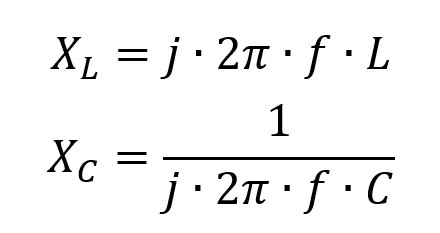
The total impedance in the AC circuit is the sum of resistance and reactance, which can be expressed as: Zin=R+jX.
When X=0, that is, the size of XL is equal to the size of XC, because the phase difference between inductive reactance and capacitive reactance is 180-in inverse correlation, so the reactance of the circuit is X=0. At this time, the impedance Zin in the circuit is the smallest, and it is purely resistive, that is, Zin=R, and the current and voltage are in phase.
When X>0, that is, XL is greater than XC, the circuit is equivalent to a series connection of a resistor and an inductor, and there is a phase difference between the current and the voltage. According to the characteristics of the inductor, U=L*di/dt, where di is the changing current on the inductor and dt is the changing time. If the input is a pure sinusoidal input voltage, there is a 90 phase difference between the current and the voltage. As shown in Figure 2, the current has the largest change slope in the whole sine when it crosses 0, while the current has a change slope of 0 at the peak. According to U=L*di/dt, when the current is at its peak, di/dt is just equal to 0. U=L*di/dt。 Then u is 0V. When the current crosses 0, the slope is the largest, and U=L* the maximum slope, so the voltage just corresponds to the peak voltage. So for inductance, the current is 90 degrees behind the voltage.
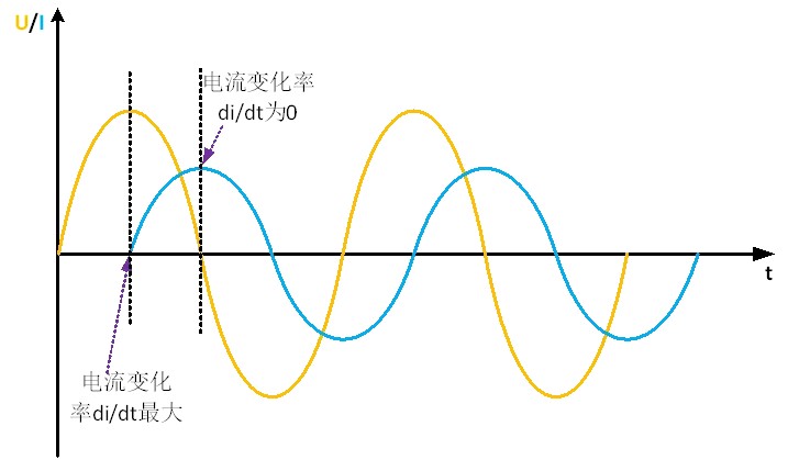
Fig. 2 waveform diagram of inductor current and voltage
If it is replaced by a capacitor, the voltage of the capacitor cannot change suddenly, but the current can change suddenly. So the capacitance and inductance are just the opposite, as shown in Figure 3, the current is 90 ahead of the voltage.
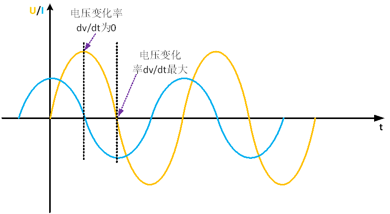
Fig. 3 waveform diagram of capacitor voltage and current
If a resistor is added in the loop, the phase of voltage and current cannot be determined, so it is necessary to introduce imaginary number to calculate. You can use j for phase, -j for 90 degrees behind, and j for 90 degrees ahead. If the impedance in the black box is j*100Ω and Vin/j100=-jVin/100, the waveforms of voltage and current can be drawn in the same coordinate system, and the current lags behind the voltage by 90. As shown in Figure 3, in the rectangular coordinate system, 1Ω is 90 degrees different from j1Ω, 1Ω is pure resistance, and j1 is 90 degrees ahead, so j100 is the positive semi-axis of the Y axis.
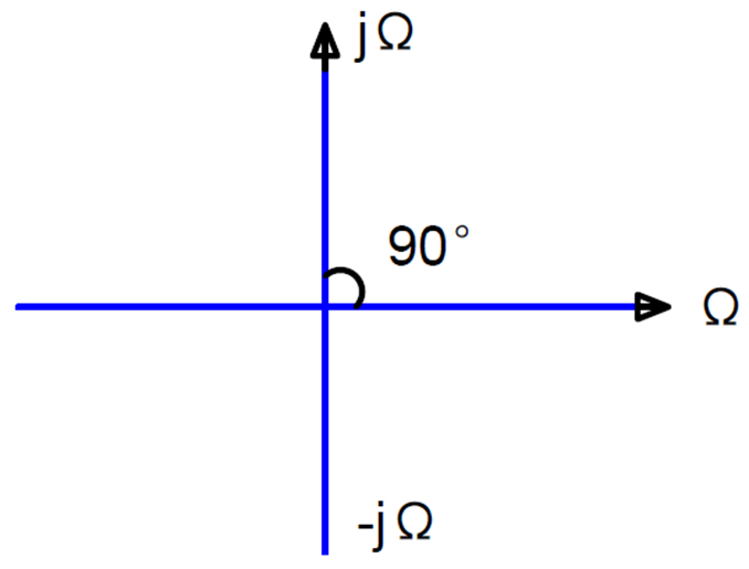
Fig. 4 Complex phase diagram