Due to the series-parallel converter (LCC structure), high cycle energy and high switching loss will occur in a wide input voltage range. In order to make the whole process work in ZVS mode, by changing the LCC resonant cavity into a double resonant network, as shown in Figure 1, the LLC resonant converter can be built by changing its C to L.
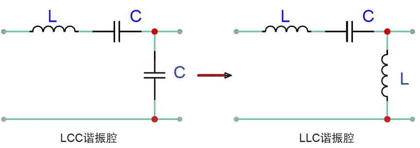
Figure 1 LCC and LLC resonant cavity
The DC characteristics of these two converters are shown in Figure 2. The DC characteristic of LLC converter is similar to that of LCC resonant converter, and it also has two resonant frequencies. In this case, Lr and Cr determine the higher resonance frequency. The lower resonant frequency is determined by the series inductance of Lm and Lr. The higher resonant frequency of LLC is in ZVS region, which means that the converter can be designed to work near this frequency, which is the resonant cavity pursued by high-frequency and high-efficiency converters.
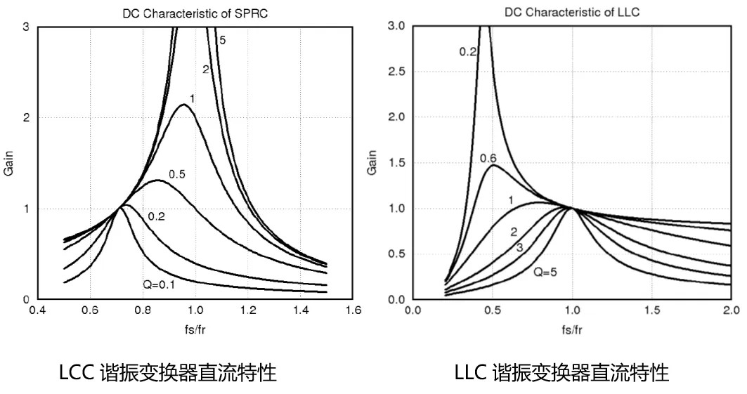
Fig. 2 DC characteristics of LCC and LLC resonant converters
Half-bridge LLC resonant converter
As shown in Figure 3, it is a half-bridge LLC resonant topology. Half-bridge switches are composed of MOSFET Q1 and Q2, Ds1 and Ds2 are parasitic body diodes of MOSFETs, and Cds1 and Cds2 are their parasitic capacitances. Lr, Lm and Cr constitute LLC resonant cavity. On the one hand, Cr stores energy to prepare for the opening of the lower pipe to transfer energy to the secondary side. In addition, it also acts as a DC blocking capacitor, balances the transformer magnetic flux and prevents saturation.
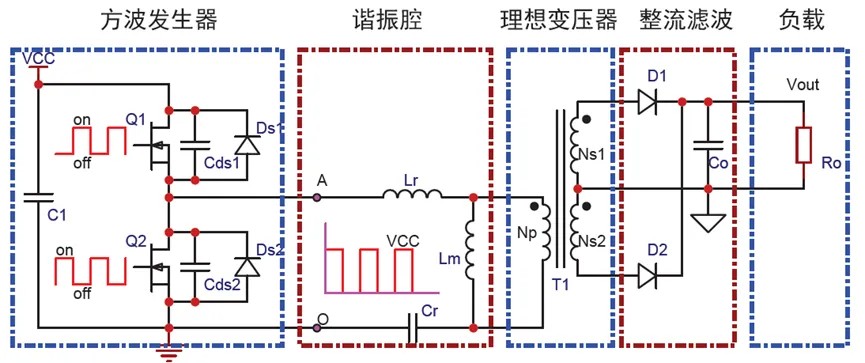
Fig. 3 Topology diagram of half-bridge LLC resonant converter
Topology analysis of half-bridge LLC-square wave generator
Vcc is usually preceded by PFC circuit output plus electrolytic capacitor smoothing output voltage, so it is a DC voltage.
A square wave generator is needed to switch the changing voltage. The duty cycle of the switch tubes of the square wave generators Q1 and Q2 are both 50%, and a square wave voltage is output, as shown in Figure 3, AO. When the upper tube is turned on, the voltage at point A is Vcc, while the upper tube is turned off. When the lower tube is turned on, point A is connected to GND, and the voltage is 0V.
Topology analysis of half-bridge LLC-resonant cavity
Resonant cavity Lr is a resonant inductor, and Lr can use the leakage inductance of transformer (integrated transformer) or an independent inductor (discrete transformer). Integrated transformer has the advantages of compact structure and small occupied volume, but its efficiency is not as high as that of discrete transformer, and the leakage inductance of integrated transformer is also quite different due to the difference of manufacturing technology, so it is difficult to control it accurately. Cr is a resonant capacitor, which plays a resonant role with Lr. Lm, which needs to be wound with a professional transformer skeleton, is the primary inductance of transformer, also called excitation inductance. Cr is a resonant capacitor, and the resonant capacitor Cr plays a resonant role together with Lr. The output voltage is constant by controlling the switching frequency, and the switching loss is reduced and the efficiency is improved by soft switching technology.
Topology analysis of half-bridge LLC-ideal transformer
The ideal transformer can realize the functions of inductance, transformer and isolation. Usually, in order to facilitate circuit analysis, the excitation inductance is separated from the ideal transformer (in fact, the inductance Lm is the primary inductance of the transformer). The ideal transformer can change the output voltage by changing the turn ratio, and transform the input voltage into the final desired output voltage, which plays the role of transmitting energy.
Topology Analysis of Half-bridge LLC —— Rectification and Filtering
For high frequency transformer, its input and output are AC quantities. Its input and output are a positive and negative square wave AC voltage. In order to get a stable output voltage, it is necessary to need a rectifier and filter circuit.
There are usually two kinds of rectifier circuits at the output end of the transformer, namely full-wave rectifier and full-bridge rectifier. The full-wave rectifier consists of two diodes, and there is a center tap in the middle of the secondary winding of the transformer as the common output (ground) of the two diodes. The full-bridge rectifier is a bridge structure composed of four diodes in a pair of common anodes. The secondary side of the transformer of the full-bridge rectifier circuit does not need a center tap, but two rectifier diodes need to be added.
Topology analysis of half-bridge LLC-equivalent circuit model
In order to facilitate the analysis, the output voltage and current are usually converted to the primary side. Fig. 4 is the equivalent circuit model of LLC topology, that is, the front square wave generator is regarded as a simple square wave power supply, the transformer is removed, only its inductance is kept, and the second half of the converter is equivalent to a resistor Ro through a simple conversion relationship. The expression of equivalent resistance can be derived from the relationship between transformer output voltage and current.

Figure 4 LLC Topology Equivalent Circuit Model