Overview of resonant converter
The resonant converter takes the resonant circuit as the basic conversion unit. When the circuit resonates, the current or voltage periodically crosses the zero point, so that the switching device is turned on or off under the condition of zero voltage or zero current, so as to realize soft switching and reduce the switching loss. Among the current resonant circuits, series resonance (SRC), parallel resonance (PRC) and series-parallel resonance (SPRC) are well known in the industry, and they are widely used in power electronic circuits because they can realize zero-voltage turn-on. However, they are not suitable for the current pursuit of higher efficiency, higher power density and higher switching frequency.
Principle of resonant circuit
Generally, the resonant circuit is an RLC circuit structure consisting of resistor (R), inductor (L) and capacitor (C). It has two basic connection modes: series connection and parallel connection, and their respective characteristics are as follows:
RLC series resonant circuit;
The basic circuit of RLC series resonance is shown in Figure 1. When the effective value of inductive reactance and capacitive reactance in the circuit is equal, that is, ωL =1/ ωC (where ω is the angular frequency), the circuit will have series resonance. At this time, the resonance frequency fo=1/LC, which is only related to the inductance and capacitance values in the circuit, and has nothing to do with the signal source. At this time, the impedance of the circuit is the minimum value R. At this time, the total voltage of the circuit is mainly added to the resistor, and the current reaches the maximum value. The circuit is purely resistive, and the current and voltage are in phase.
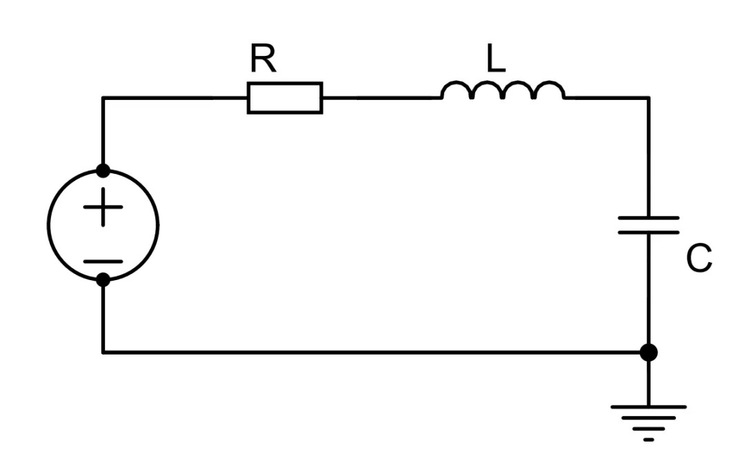
Fig. 1 Basic circuit of RLC series resonance
RLC parallel resonant circuit;
The basic circuit of RLC parallel resonance is shown in Figure 2, which is similar to series resonance. Resonance occurs when ωL =1/ ωC is satisfied, where ω is the resonant angular frequency. When resonance occurs, the admittance of the circuit is the smallest, the equivalent impedance is the largest, and the effective value of the voltage is the largest when the excitation current is constant.
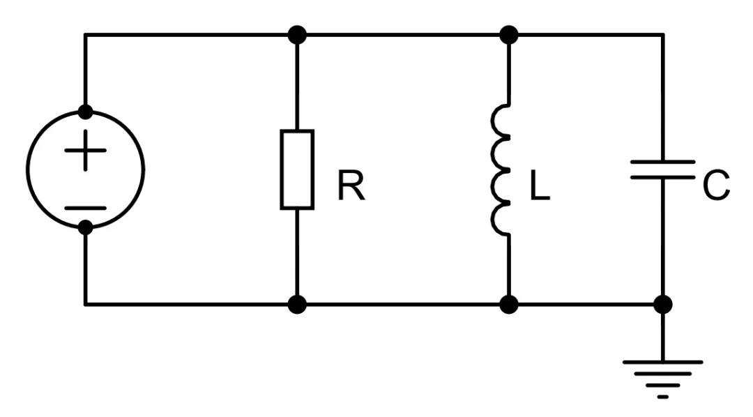
Fig. 2 Basic circuit of RLC parallel resonance
Series resonance (SRC) converter
The schematic diagram of the half-bridge series resonant converter is shown in Figure 3. The resonant inductor Lr and the resonant capacitor Cr are connected in series to form a series resonant cavity, which is connected in series with the load. In this structure, the resonant cavity and the load act as a voltage divider. By changing the frequency of the input voltage Va, the impedance of the resonant cavity will be changed, which will separate the input voltage from the load. As it is a voltage divider, the DC gain of SRC is always lower than or equal to 1. Therefore, under light load (large Rload), in order to ensure the stability of the output voltage, the switching frequency often needs to rise to a high level, which is not conducive to the stability of the system. If the converter runs at no load, the output voltage will be uncontrollable.
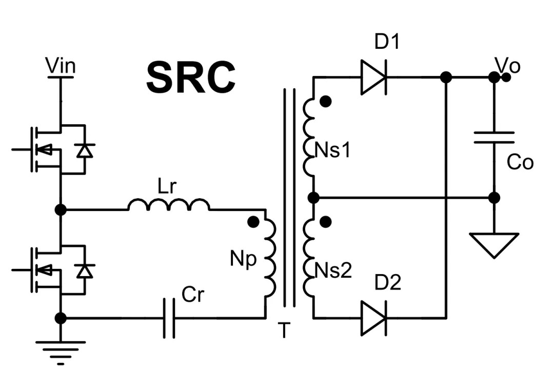
Fig. 3 Circuit diagram of SRC converter
As can be seen from Figure 4, different Q-value curve clusters all occur at the resonant frequency, and the gain is 1. When the switching frequency is lower than the resonant frequency, the impedance of the resonant network is capacitive, and MOSFET can realize ZCS; at this time; When the switching frequency is higher than the resonant frequency, the impedance of the resonant network is inductive, and MOSFET can realize ZVS; at this time; For MOSFET, to realize ZVS, the converter must work above the resonant frequency. In addition, it can be seen from the operation Region that with the increase of input voltage, the converter works at a higher frequency away from the resonance frequency. With the increase of frequency, the impedance of the resonant cavity increases. Because the resonant cavity does not participate in power conversion, if its impedance is high, the energy in the resonant cavity is higher, which is purely circulating exchange (returning to the input end, reactive power) and increases the current stress of MOSFET.
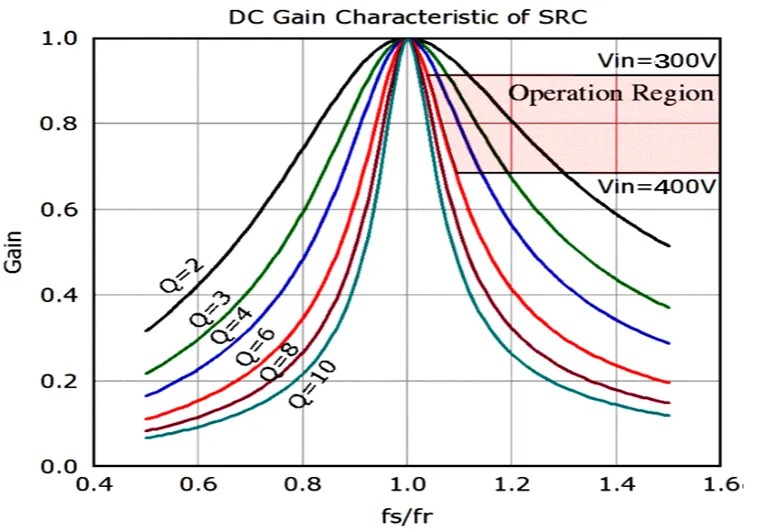
Fig. 4 Relationship between Q, gain and normalized frequency of SRC
Through the above analysis, SRC is not an ideal choice for efficient DC-DC. The main problems are: output regulation under light load, turn-off current under high cycle energy and high input voltage.
Parallel resonant (PRC) converter;
The circuit of the half-bridge parallel resonant converter is shown in Figure 5. For a parallel resonant converter, the load is connected in parallel with the resonant capacitor.
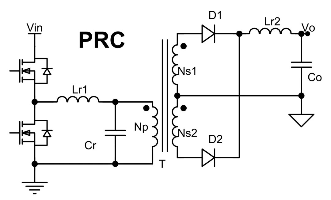
Fig. 5 Parallel resonant converter
Similar to SRC, the working frequency of the converter is also higher than the resonant frequency to realize ZVS. As can be seen from Figure 6, its working range is very small, and its frequency variation range is not large under light load (small q). However, due to the small equivalent input impedance, a big problem is that the circulating energy is very high, which leads to the large conduction loss of MOSFET.
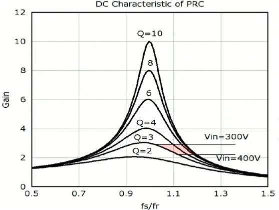
Fig. 6 relationship between q, gain and normalized frequency of PRC
Through the above analysis, PRC is not an ideal choice. The main problems are: large cycle energy and high turn-off current at high input voltage.
Series-parallel converter (SPRC);
The schematic diagram of the series-parallel resonant converter is shown in Figure 7. The resonant cavity of SPRC can be regarded as the combination of SRC and PRC. For SPRC, it combines the excellent characteristics of PRC and SRC. Through parallel capacitor Cpr, SPRC can adjust the output voltage under no-load condition. Connecting the load in series with the resonant cavity can reduce the circulating current.
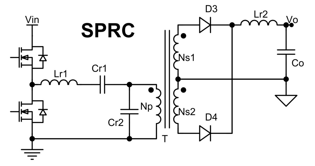
Fig. 7 Series-parallel resonant converter
As can be seen from Figure 8, SPRC has two resonant frequencies, but the same operating frequency needs to be greater than the resonant frequency to realize ZVS. However, between these two resonant frequencies is the ZCS working range, which leads to a narrower working range of the converter. Like SRC and PRC, the converter works around the resonant frequency of 300V V. At high input voltage, the converter works at a higher frequency far from the resonant frequency.
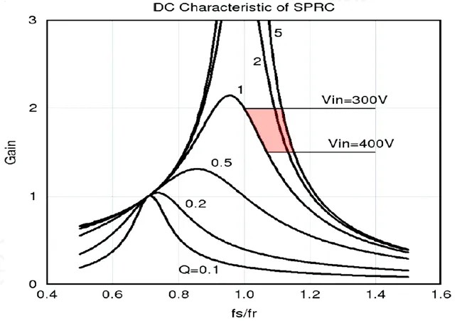
Fig. 8 relationship between q, gain and normalized frequency of sprc
Through the above analysis, although the SPRC cycle energy is small, it is not sensitive to load changes. However, for wide input range design, SPRC will still bring great loss.
Through the analysis of SRC, PRC and SPRC converters, it is concluded that these three converters can not solve the problems of circulating current and frequency increase when high voltage is input. Resulting in high conduction loss and switching loss. High efficiency and high frequency are the eternal goals of designing resonant converters, so it is necessary to find other derived topologies on this basis.