Origin of LLC converter
In the traditional hard switching circuit, the switching loss is large, and with the increase of working frequency, the loss problem becomes more and more prominent, which limits the improvement of power conversion efficiency and the miniaturization of equipment. In order to solve these problems, researchers began to explore soft-switching technology, and resonant converter is an important form of soft-switching technology. LLC resonant converter, as a typical resonant converter, was originally proposed to achieve more efficient energy conversion and lower switching loss.
However, for a long time after its birth, LLC resonant converter has not been widely used because of complicated control and complicated parameter design, but is mainly limited to some specific fields that require extremely high power supply performance, such as high-voltage power supply or high-end audio system. In recent years, with the development of semiconductor device manufacturing technology, the performance of switching tube is constantly improved, and the demand for high-efficiency and miniaturized power supply for electronic equipment such as flat-panel TV is increasing sharply, LLC resonant converter has begun to attract widespread attention and gradually become a mainstream topology. Nowadays, LLC resonant converter has been widely used in various electronic equipment, charging piles, server power supply and other fields.
Zero voltage switching (ZVS) and zero current switching (ZCS)
For resonant converters, zero-voltage switching (ZVS) and zero-current switching (ZCS) are two important soft-switching technologies in power electronics technology. The following is an introduction to them:
Zero voltage switch (ZVS):
Mainly based on the characteristics of capacitor charging and discharging and the resonance phenomenon in the circuit. Before the switch tube is turned on, the voltage at both ends of the switch tube is made to resonate to zero through a resonant circuit or other control means, and then a turn-on signal is applied at the moment when the voltage is zero, at which time the switch tube is turned on with minimal loss. During turn-off, due to the existence of capacitors at both ends of the switch tube, the voltage can also change relatively gently, which is similar to zero-voltage turn-off (there is actually a certain turn-off loss, but it has been greatly reduced compared with hard switching). The ZVS turn-on timing is shown in Figure 1, and the actual ZVS turn-on waveform is shown in Figure 2.
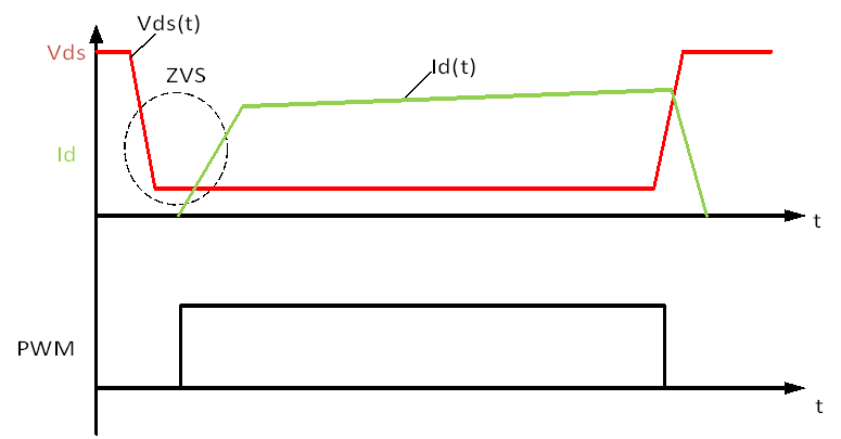
Figure 1 ZVS turn-on timing
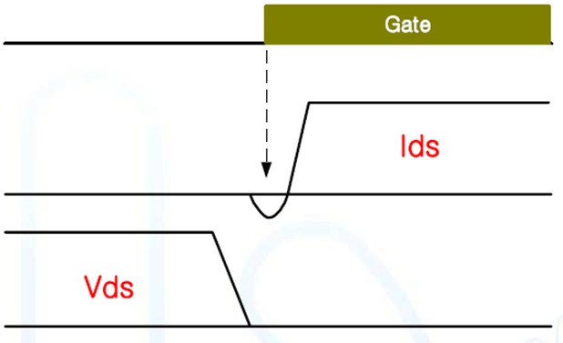
Figure 2 Actual waveform of ZVS on
As can be seen from the waveform, in the process of MOSFET from turn-off to turn-on (including the process of discharge of drain-source junction capacitance Cds, turn-on of body diode, slow turn-on of MOSFET, etc.), because the drain-source voltage Vds of MOSFET is close to zero, the voltage and current overlap in the switching process can be significantly reduced, so the switching loss is relatively low. The conduction los of that MOSFET is approximately zero. When turning off, we can see that the current and voltage are still maintained at a high level during the conversion process, so there is a turn-off loss.
Zero current switch (ZCS):
By controlling the direction or magnitude of the current, the switch can be turned on or off when the current crosses zero. Before the switch tube is turned off, the current flowing through the switch tube is gradually reduced to zero by control strategy, and then the turn-off signal is applied at the moment when the current is zero, at which time the switch tube is turned off with minimal loss. When switching on, it is also necessary to ensure that the current is zero, which can reduce the current impact when switching on. The turn-on timing of ZCS is shown in Figure 3, and the actual turn-on waveform of ZCS is shown in Figure 4.
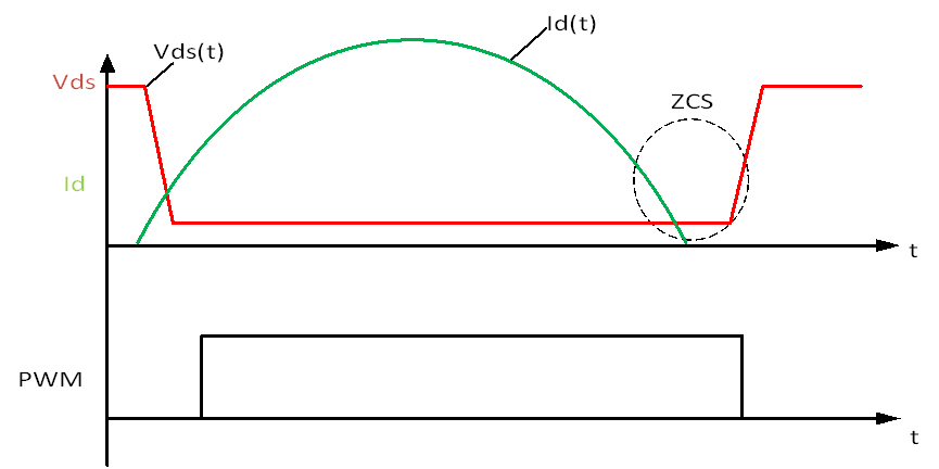
Figure 3 ZCS turn-on timing
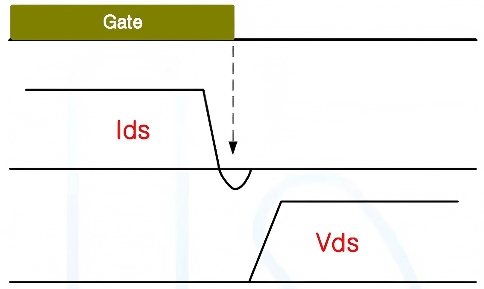
Figure 4 Actual waveform of ZCS on
It can be seen from the waveform that the current has dropped to zero before the MOSFET is turned off, so the switching loss can also be reduced. However, the reduction degree of switching loss may vary according to the specific implementation.
Because of the existence of soft switching, the changes of voltage and current in the switching process are small, and the switching noise is also reduced, so the electromagnetic radiation and electromagnetic interference performance are excellent. This is different from the "seesaw" relationship between EMI and efficiency in conventional PWM converters. Specifically, resonant circuits can achieve soft switching process to a certain extent. As shown in figure 5, the soft-switching waveform of the half-bridge harmonic circuit.
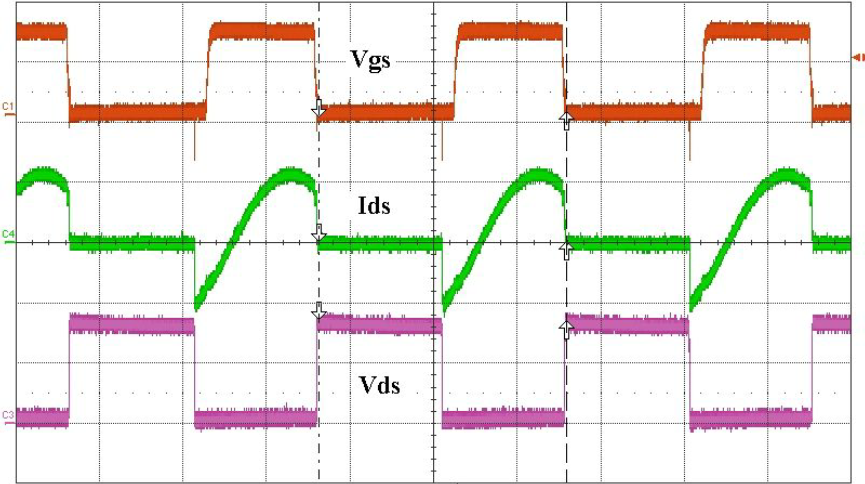
Fig. 5 Soft-switching waveform of typical half-bridge harmonic circuit