Foreword
IGBT is composed of MOSFET and BJT. Compared with other high-power switching devices, IGBT has the advantages of low driving power, high current, no secondary breakdown effect and easy parallel connection. Therefore, IGBT is widely used in white goods, servo motors and new energy power generation systems. However, when overcurrent or short circuit occurs in some special working conditions, the current flowing through the device is several times of the normal rating, and the junction temperature of the device die rises rapidly, which leads to the damage of the device, so the peripheral circuit or driver must quickly judge and cut off the driving signal.
At present, the industry is divided into two types according to the time when the short circuit occurs and the short circuit in IGBT working state, namely, the first type short circuit (SC1) and the second type short circuit (SC2).。
Short circuit type
SC1 short circuit: the IGBT has been short-circuited before it is turned on, that is, before the IGBT channel is turned on, the IGBT is turned off, and then the gate voltage Uge controls the channel to be turned on, and the large current from the high-voltage bus is injected into the IGBT channel. At this time, the current flowing in the channel can be considered as the short-circuit current of IGBT, and the relevant waveform during short-circuit is shown in Figure 1.
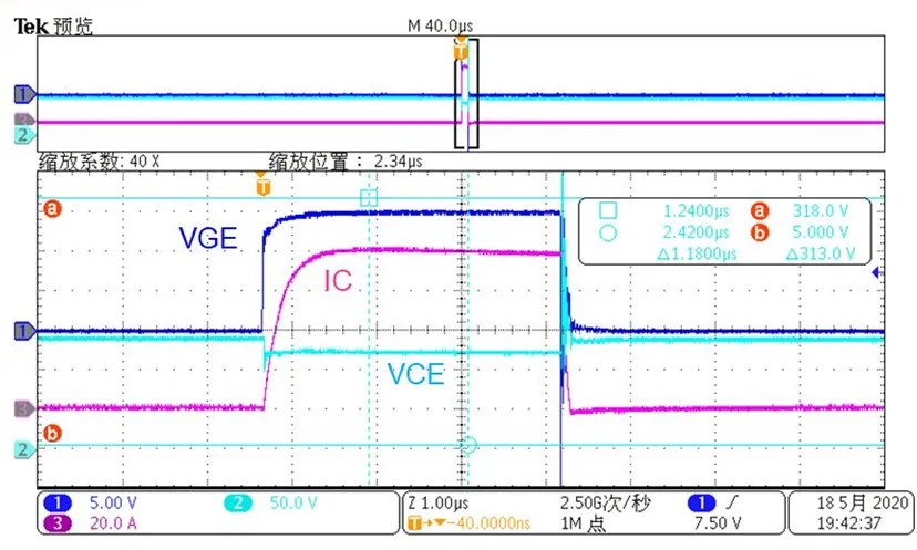
Figure 1 SC1 Short Circuit Waveform
The resulting short-circuit current changes with time and temperature. As the temperature Tvj increases, the transconductance will decrease, and the short-circuit current Isc will decrease. On the other hand, the short-circuit current is also a function of the gate voltage when a short-circuit occurs. Figure 2 shows the relationship among the gate voltage, short-circuit current and the maximum short-circuit time of Yaoxin 1200V 75A IGBT.
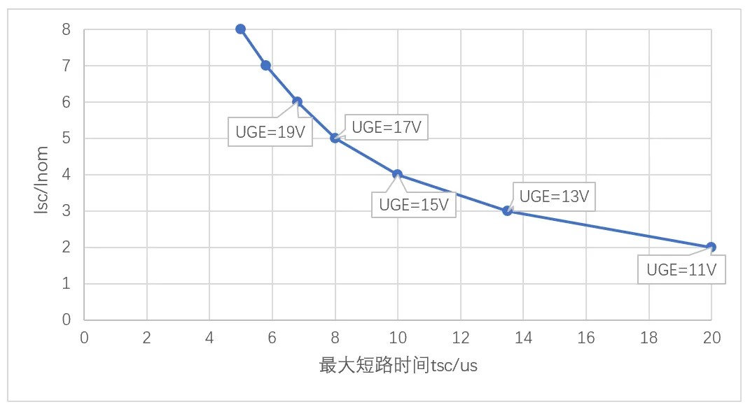
Fig. 2 Relationship among gate voltage, short-circuit current and maximum short-circuit time
SC2 short-circuit: Short-circuit after IGBT is turned on means that during the turn-on process of IGBT, the voltage drop Uce between collector and emitter quickly enters the desaturated voltage state from the low turn-on voltage (saturated voltage) state, and at this time almost bears the sum of all bus voltage Udc and voltage spikes caused by commutation path inductance. For example, IGBT is often used in half-bridge structure. In the process of commutation between upper and lower tubes, it is usually caused by cross talk that leads to misleads and leads to short circuit (direct connection) in the bridge arm. In this case, the inductance in the short circuit loop is small (generally tens of nH), and IGBT generates huge current and generates a lot of heat instantly, thus damaging the chip and packaging materials, and even burning.
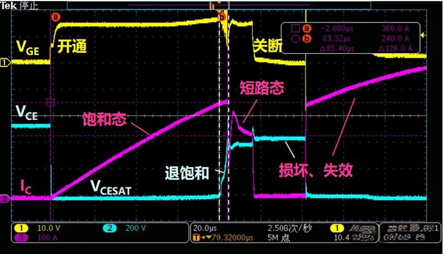
Fig. 3 waveforms of sc2 short-circuit gate voltage, saturation voltage and short-circuit current
This sudden change in voltage will charge the gate Miller capacitor, which may lead to a further increase in the gate voltage and a further increase in the collector current according to the transconductance of IGBT. Based on the above two short-circuit conditions, a quick and accurate protection scheme must be adopted.
Short circuit protection method
Detecting on-state voltage drop Uce:
- Principle: In normal operation, IGBT is in the saturation region of conducting state, at which time Uce is low, generally about 1.5V. When a short-circuit fault occurs, the collector current of IGBT rises sharply, leaving the saturation region and entering the linear working region, which leads to the rapid rise of Uce voltage. By monitoring the change of voltage value of Uce, it can be judged whether IGBT is short-circuited.
- Protective action: When it is detected that the Uce voltage exceeds the set protection threshold, the protection circuit takes action immediately. One way is to reduce the driving voltage to a lower value (for example, 8V), so that the IGBT will be transferred from the saturated state to the amplification region, and the on-state resistance will increase and the short-circuit current will decrease. Continuously detect Uce after a period of time (such as 4μs), and if it returns to normal, restore the driving voltage to normal; If the Uce does not return to normal, turn off the drive signal to reduce the collector current to zero, realize the soft turn-off of short-circuit current, and avoid the IGBT from being damaged by excessive di/dt caused by rapid turn-off.
Bus shunt resistance detection method:
- Principle: A small resistor is connected in series on the bus. When a short circuit occurs in the circuit, a large current will flow through the resistor, resulting in a voltage drop across the resistor. By measuring this voltage drop, it can be judged whether a short circuit fault occurs.
- Advantages and disadvantages: This method has the advantages of high accuracy and sensitivity, and can detect the short circuit of bus circuit; The disadvantage is that it is only suitable for low-power equipment. For high-current application scenarios, the power consumption on the resistor is too large, which may lead to overheating or even damage of the resistor.
Output hall detection method:
- Principle: Hall sensor is used to detect the current at the output end of IGBT. Hall sensor can convert the current signal into a proportional voltage signal, and judge whether the current exceeds the normal range by monitoring the voltage signal, so as to determine whether the short circuit fault occurs.
- Advantages and disadvantages: Hall sensor has a fast response speed and can monitor the current change in real time. However, its cost is relatively high, and problems such as magnetic field interference should be paid attention to during installation and use, otherwise the accuracy of detection may be affected.
Optical coupling protection method:
- Principle: By detecting the Uce of IGBT, according to the relationship between Uce and collector current Ic, when Ic rises rapidly, Uce will also rise. When the Uce value rises to the protection point voltage, the optocoupler will automatically turn off and send an error signal to the control circuit to trigger the protection action.
- Features: This protection method has high sensitivity, but relatively poor accuracy, and is usually only suitable for short-circuit protection.
To sum up, the short-circuit protection of IGBT is a complex but vital field, which involves many levels of protection measures, including hardware design, gate drive strategy and software control technology. Through these methods, it can be ensured that IGBT can respond quickly in the face of short circuit, thus protecting the whole system from damage.
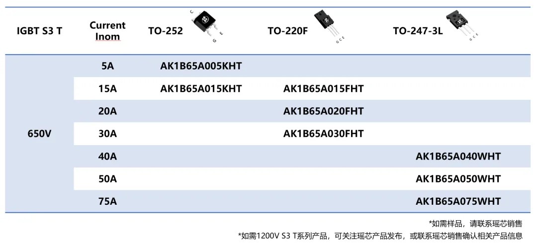
AKS 650V S3 IGBT T series product recommendation