Foreword
As we all know, Synchronous Rectification, SR) is a new technology which uses power MOSFET with very low on-state resistance instead of rectifier diode to reduce the loss. It can greatly improve the efficiency of power supply and improve the power supply index by taking advantage of its secondary side, which is in line with the development trend of miniaturization, high energy efficiency and intelligence of switching power supply. In high-power mobile phone fast charging and adapter, the mainstream solution is still flyback synchronous rectification topology. The challenge is to make a reliable control strategy and drive circuit, and to highlight its advantages to the maximum, so as to improve the efficiency of the whole machine.
Basic principle of flyback synchronous rectification
Synchronous rectification uses MOSFET to rectify the output current. Compared with the relatively fixed forward voltage drop of traditional diodes, the voltage drop of MOSFET is proportional to the current and on-resistance, as shown in Figure 1. As the turn-on voltage of MOSFET is reduced, the turn-on loss of rectifier circuit power devices can be greatly reduced. For low-voltage and high-current output applications, better efficiency and heat dissipation performance can be achieved than traditional diode rectification by selecting SR MOSFET with ideal on-resistance.
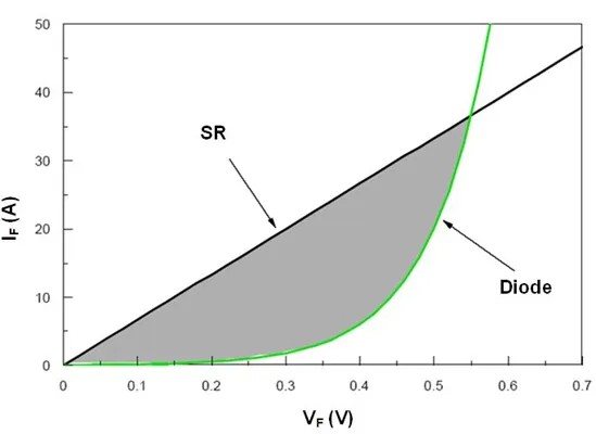
Fig. 1 Conduction characteristics of Sr and diode
Its working principle is that by controlling the turn-on and turn-off of MOSFET, it can be turned on at an appropriate time, so as to realize low-resistance current flow.
Specifically, when the voltage induced by the secondary winding of the transformer causes the current to flow out of the secondary winding, the driving circuit of the synchronous rectification MOSFET will control the MOSFET to conduct, and the current will flow through the MOSFET at this time. Because the on-resistance of the MOSFET is very small, the on-loss is greatly reduced and the efficiency of the power supply is improved, as shown in Figure 2. When controlling the synchronous rectifier MOSFET, it is necessary to accurately detect the voltage and current state of the secondary winding to ensure that the MOSFET can be turned on and off at the right time, so as to avoid short circuit or reverse current.
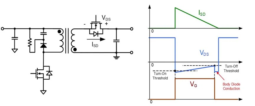
Figure 2: Basic working principle of flyback SR solution
Synchronous rectification control method
At present, most synchronous rectifier controllers drive SR MOSFET based on direct detection of drain-source voltage (VDS), because it does not need to communicate with the primary side, which reduces the total BOM cost. As shown in fig. 3, the turn-on and turn-off of SR MOSFET are usually controlled by two negative voltage thresholds. They are the turn-on threshold (-80mV) and the turn-off threshold (-3mV), which can ensure that the SR MOSFET is always safely turned off when it is reversely biased.
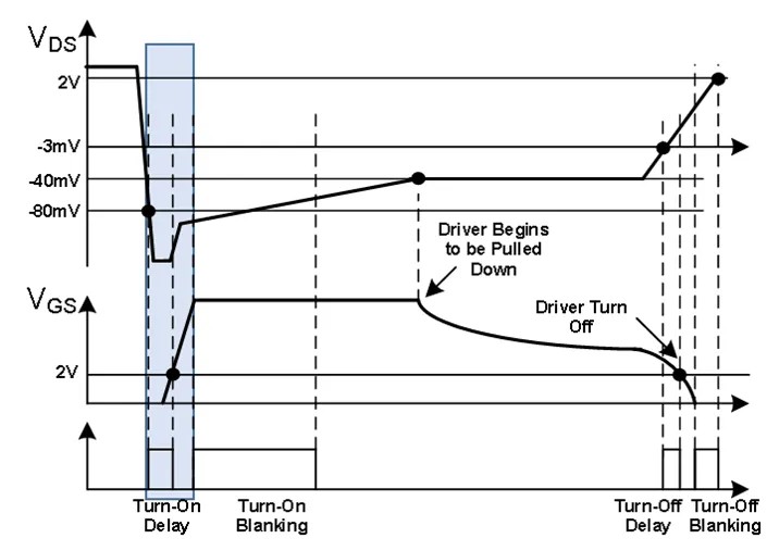
Figure 3: Basic working principle of flyback SR solution
Influencing factors of efficiency
As can be seen from fig. 3, the body diodes at both ends have a very short on time, just before the SR MOSFET is turned on and after it is turned off. Therefore, timing control is very important for SR controller, because the on-time of these two diodes will increase the extra on-loss (the longer the time, the more serious the loss).
SR early turn-off: If the SR early turn-off time is too long, it may lead to serious reverse recovery current after SR turn-off due to the poor characteristics of MOSFET body diode. Fig. 4 shows that the reverse recovery current of the body diode of SR MOSFET rises to 9A due to the early turn-off of SR by 400ns, and the high voltage peak of 80V is caused by leakage inductance. Therefore, the early turn-off of SR MOSFET will not only bring extra conduction loss and reduce efficiency, but also bring greater peak stress and stronger EMI noise source due to greater reverse recovery current.
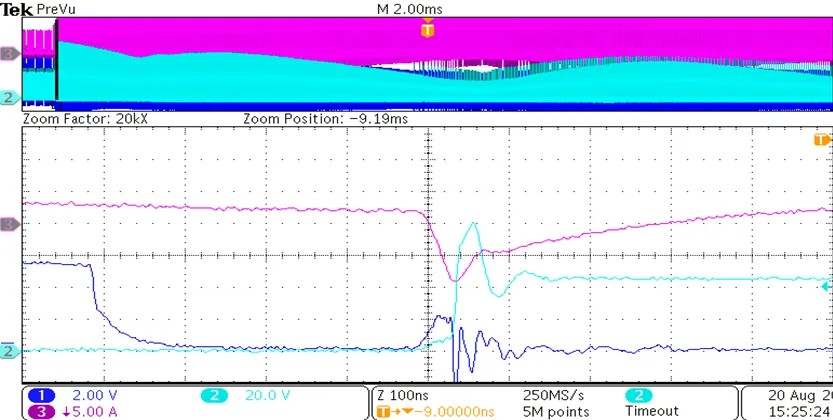
Figure 4: High Peak Current and Voltage Caused by SR Early Shutdown
SR delayed shutdown: If SR is turned off late, the same problem as early turn-off will occur. When the energy transmission or driving of the primary and secondary sides is delayed, the SR is turned off and the output current is backfilled. If SR is turned off for too long, it will lead to the simultaneous conduction of primary and secondary MOSFET, and make the primary and secondary MOSFET go straight through in a short time. As shown in fig. 5, when the SR is turned off, the negative current rises to as high as 10A, resulting in a high voltage spike of 87V after the SR MOSFET is turned off. Therefore, the early turn-off of SR MOSFET will not only bring about the problems of low efficiency and large stress during turn-off, but also bring about the serious through problem of primary and secondary sides.
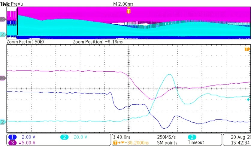
Figure 5: High Peak Current and Voltage Caused by SR Turn-off Delay
In order to alleviate these problems, it is very important to accurately control the turn-on and turn-off time of Sr. At the same time, the peripheral driving parameters of MOSFET can also be optimized. The common optimization methods are as follows:
1.Increase that RC absorption of MOSFET, Usually, C increases or R decreases (RC absorption is lossy, and it will also bring a little efficiency loss if the parameters are not matched well).
2.Increase the primary MOS drive resistance, Slow down the conduction rate, use Miller effect to transfer power, and achieve the purpose of reducing or even completely eliminating the voltage spike of the secondary diode.
3.Minimizing leakage inductance and reducing the driving resistance of SR MOSFET can alleviate a series of problems caused by delayed turn-off.
As shown in Figure 6, by accurately controlling the turn-on and turn-off timing and matching with appropriate peripheral parameters, the current and voltage (4A and 62V respectively) have only a relatively low peak, which is very effective for reducing EMI noise and improving power efficiency.
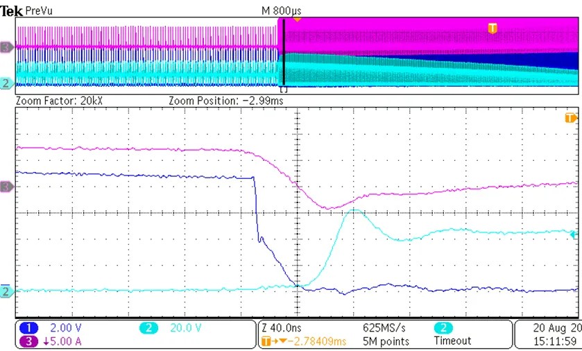
Figure 6: Precise control and appropriate peripheral parameters ensure low peak current and voltage.
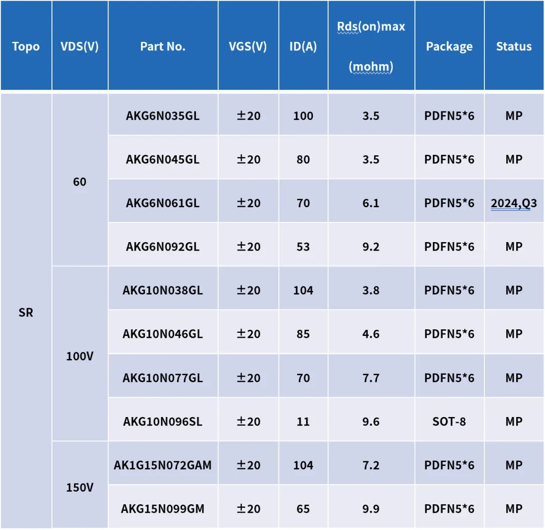
Flyback SR MOSFET with Alkaidsemi