Foreword
Brushless motor has been widely used in various fields because of its advantages of high torque, long life and low noise. Its internal electronic winding can be regarded as an inductive coil. With the internal structure and current waveform shown in Figure 1, the magnetism of the electromagnet is changed by constantly changing the current direction in the stator winding, so that the motor rotates continuously. Therefore, it is necessary to design a driving circuit to change the current direction in the stator winding to make the rotor rotate. The commonly used driving circuit is a three-phase full-bridge inverter circuit.
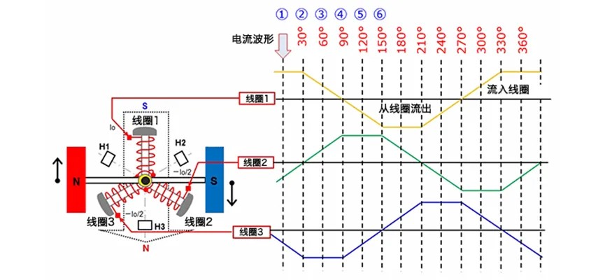
Fig. 1 Internal stator winding structure and current waveform of motor
Three-phase full-bridge inverter circuit
The brushless motor drives the three-phase full-bridge inverter circuit and its working sequence as shown in Figure 2. There are three windings in the brushless motor, which are U, V and W phase windings respectively. There are two directions of current in each winding, so there are 3*2=6 directions of current in the three-phase motor. By controlling the directions of current in the three windings in the three-phase bridge circuit, the direction can be changed according to certain rules, so as to realize the continuous operation of the three-phase motor. By controlling the different duty cycle of PWM signal, the change of output voltage is realized to control the speed of motor.
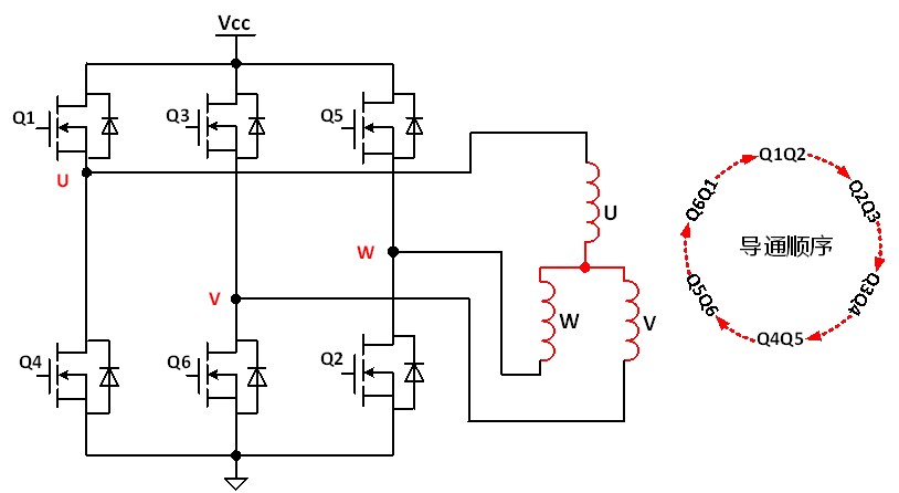
Fig. 2 Three-phase full-bridge inverter circuit and its working sequence
As shown in fig. 3, in the turn-on sequence of Q1 and Q2, Q1 keeps Hengtong, and Q2 uses PWM chopping (it is also possible to keep Q2 Hengtong and use PWM chopping, but it is difficult to realize high-side PWM driving in this way). If the duty ratio of PWM is 50%, the average voltage across the motor winding is Vcc*50%.
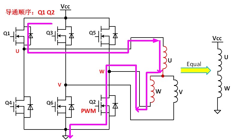
Fig. 3 Q1 Q2 turns on sequential circuit flow
When Q1 is turned on and Q2 is turned off, the direction and magnitude of the current should be kept unchanged due to the inductance characteristics of the winding. At this time, the winding is equivalent to a current source, and the current starts from the positive end W of the source, continues through the Q5 body diode D5, and returns to the negative end U of the source, as shown in Figure 4. The voltage between two points AB is clamped at 0.7V by D5. At this time, the power consumption of MOS tube is called freewheeling loss, and the calculation formula of freewheeling loss is P=0.7V*Id.
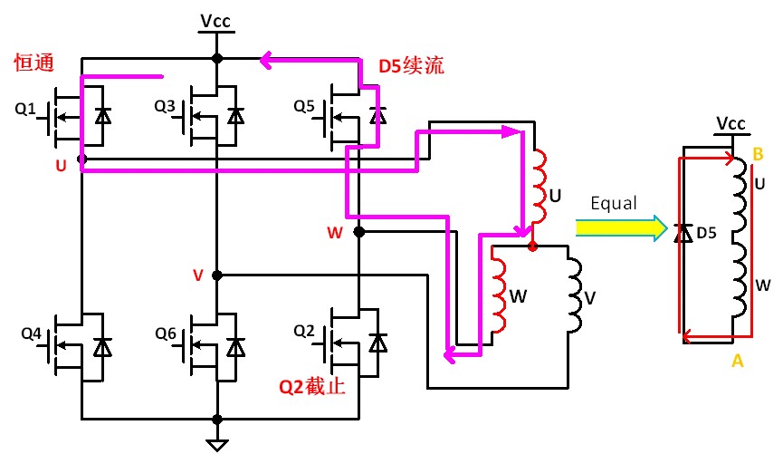
Fig. 4 Q1 Q2 turns on sequential circuit flow
Heat loss analysis
Take the first step of turning on the phase sequence Q1 Q2 as an example, and the total time is from t1 to t4 (single sequence works 60), as shown in Figure 5. During the period from t1 to t4, Q1 has only conduction loss (ignoring the first turn-on loss and the first turn-off loss), while Q2 has switching loss and conduction loss. Q5 parasitic diode D5 has freewheeling loss.
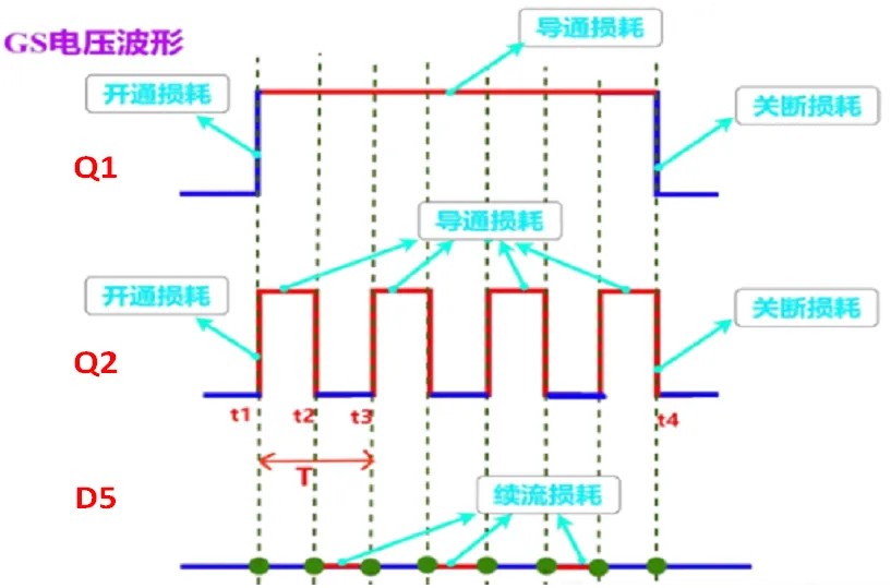
Fig. 5 Composition of Turn-on Timing Loss in the First Step
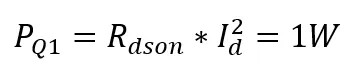
Take an electric bicycle as an example, the Vcc supply voltage is 48V, the current Id in the loop is 10A, the duty ratio is 50%, and the switching frequency is 20kHz. Assuming that the on-resistance of MOS transistor Rdson=10mΩ, Q1 has only on-loss in the phase sequence from t1 to t4:
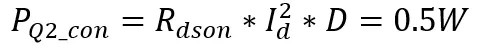
The loss of Q2 includes turn-on loss, turn-on loss and turn-off loss. First, look at the loss in a PWM cycle. When PWM is at a high level, Q1 and Q2 are turned on at the same time. Assuming that the duty ratio of PWM is 50% and the period of PWM is t, then the turn-on loss of Q2 during the period from t1 to t2 is:
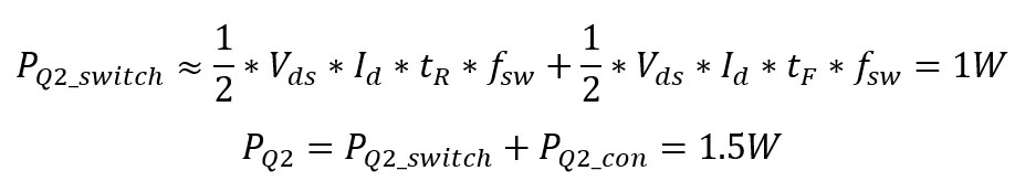
Assuming the switching loss of 100ns, Q2:
Voltage drop of diode is 0.7V, and freewheeling loss of D5:

In the first turn-on phase sequence, the freewheeling loss is greater than the switching loss, Q5 is the hottest, Q2 is the second, and Q1 is the lowest. For example, in other low-power applications, when the current in the loop flows through 1A, the parasitic diode's free-wheeling loss is 0.35W, Q2 is the hottest, D5 is the second, and Q1 is the lowest.
Based on the comparison between the above low power and medium power, there is a law: when the current is low, whoever chops it will be hot; When the current is high, whoever continues to flow will be hot.
Comparison of afterflow modes
During the period from t2 to t3, Q1 is on, Q2 is off, and Q5 is off. At this time, the current flows through the body diode of Q5, and the voltage across the inductor is clamped at 0.7V. Therefore, 0.7V=L*di/dt, and di/dt = 0.7V/L.. At this time, di/dt is very small, that is, the change speed of current is very small. This shows that during the period from t2 to t3, the freewheeling current of the inductor drops very slowly, which is called slow freewheeling, also called high-end freewheeling. For the motor, the motor can only output torque when there is current on the motor winding. Because the Id current drops slowly during slow freewheeling, it takes a long time for the current to drop to zero, which ensures that there is still current on the motor winding during freewheeling, that is, the motor can still output torque during freewheeling. However, sometimes it is not expected that the motor winding still has a large current in the freewheeling device. For example, mainstream new energy vehicles all have energy recovery function, that is, when braking, the current on the motor winding needs to be reduced to zero in a short time. At this time, fast freewheeling is needed to make the current change quickly, and the current can become zero in a short time, and the energy is fed back to the input power supply.
As shown in fig. 6, the inductor freewheeling turns off Q1 and Q2. At this time, the current will freewheel through the body diodes of Q5 and Q4, and the current will form a loop through the input power supply. At this time, the input power supply is charged, because the W terminal comes out and passes through the body diode D5 of Q5, with a voltage drop of E+0.7V, and then it is connected to the input power supply, so the W terminal is E+0.7V.. The body diode D4 of Q4 through which GND passes has a voltage drop of 0.7V, and then it is connected to the negative terminal (U terminal) of the inductor, so the U terminal of the inductor is -0.7V, and the induced electromotive force of the inductor is E+0.7V.. According to the formula: U/L=di/dt, 0.7V for slow afterflow and E+0.7V for fast afterflow. The result of di/dt is much larger than that of slow freewheeling, when the current changes rapidly.
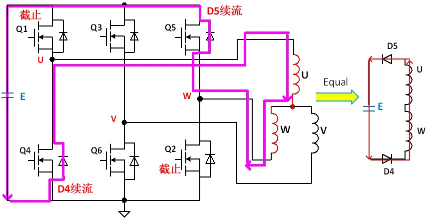
Fig. 6 fast freewheeling circuit diagram