Foreword
Unmanned aerial vehicle (UAV) started in the military field. In recent years, thanks to the expansion of territory in the civilian market, the penetration of UAV is increasing, and it is defining a brand-new "low-altitude economy" that is different from the traditional aviation industry. The electronic governor, which is the core component, is regarded as the "brain" of the UAV. Its main function on the UAV is to convert DC into AC, and control the motor speed according to the data signal received by the throttle controller.
Technical characteristics of unmanned electromechanical adjustment
The main power circuit of the driving motor in the electro-hydraulic control system is a three-phase full-bridge inverter circuit, which is usually powered by a battery (3S-8S battery voltage is 11.1-33.6V) and converted into three-phase alternating current for the brushless motor. As shown in Figure 1, the main circuit structure diagram of the electro-hydraulic control system is unmanned. Because the battery voltage is very low and the torque of the motor driving the propeller is very high, in order to meet the output requirements, the output current of the three-phase inverter is very large, so the inverter driving the motor system of UAV needs to adopt a low-voltage and high-current three-phase inverter.
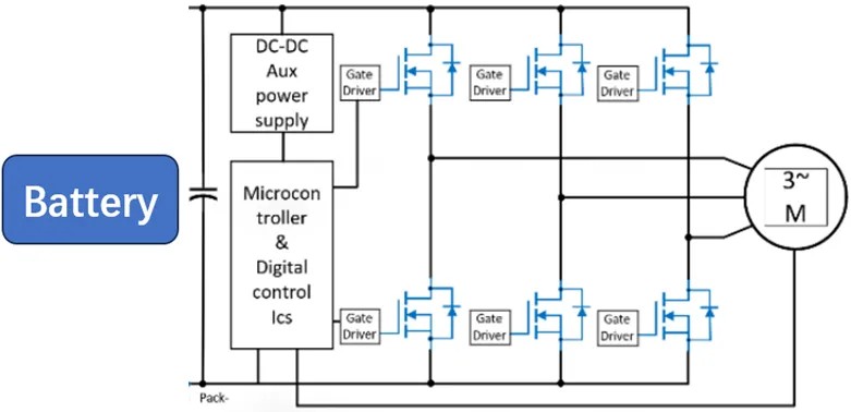
Fig. 1 Structure diagram of main circuit of unmanned electromechanical regulator
Requirements of MOSFET in electric adjustment
The MOSFET tube in unmanned electro-mechanical tuning plays a key role in the aspects of battery life improvement and electro-mechanical tuning performance. Therefore, there are still the following outstanding problems to be solved when using low-voltage and high-current three-phase inverter circuits:
1. Based on the application scenario of UAV, the inverter circuit not only needs high power density, but also requires the inverter to have high reliability to meet various complex flight environments.
2. Because the inverter current is large, in order to reduce the conduction loss and voltage drop of MOSFET, it is necessary to choose a switching device with a small Rds_on, and the device model with a small Rds_on generally has a low withstand voltage. dv/dt caused by stray inductance in the switching process may lead to voltage breakdown of the switching device, thus damaging the equipment. Therefore, it is necessary to reduce the influence of stray inductance, restrain the voltage overshoot in the switching process and prevent the MOSFET voltage breakdown through reasonable design or taking additional measures.
3. Due to the sudden acceleration and deceleration of the UAV or the unexpected stall during the flight, the current flowing through the MOSFET instantly becomes several times larger. In order to ensure that the UAV does not stall at high current, it is necessary to consider the ability of the device to quickly turn off at high current.
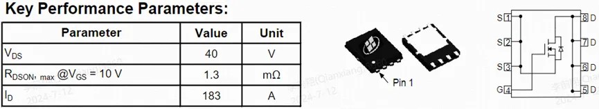
Based on the above application characteristics, Yaoxin Micro has introduced a special MOSFET for UAV, which adopts a shielded gate trench MOSFET AK1G4N013G-T. The device Rds_on has a maximum of 1.3 mOhm, a voltage of 40V, a DFN5X6 package, and has the characteristics of super current turn-off capability and strong avalanche resistance.
Avalanche characteristics
The device has super avalanche capability. The avalanche waveform is tested by using double pulse test under the conditions of Rg=0Ω and L=2.5uH, as shown in Figure 2, =435.3A, avalanche time 12us and avalanche energy.
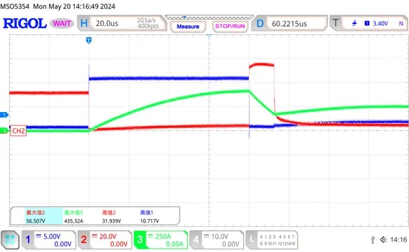
Figure 2 Avalanche test waveform
High current fast turn-off characteristics
The device has the ability of fast turn-off at high current, and it is also tested with double pulse test at Rg=0Ω and L=6uH. The working waveform of fast turn-off at high current is as shown in Figure 3. The current of MOSFET reaches 777A when it is turned off, and the device still turns off at super-large di/dt, and works in the linear region during the turn-off process.
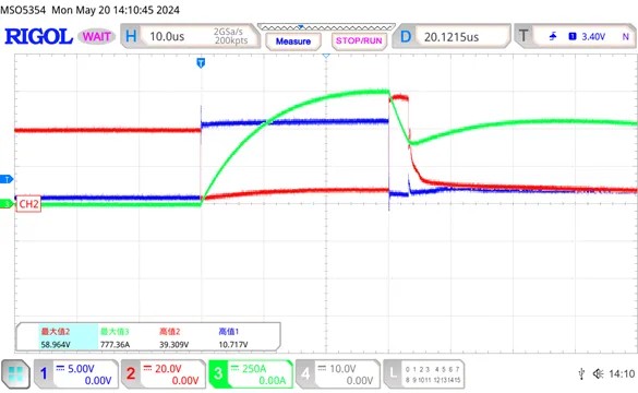
Fig. 3 waveform of high current turn-off test
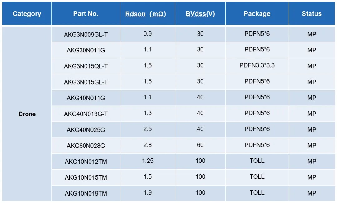
Recommended model for unmanned electromechanical adjustment application: